
To find the flat length of a sheet metal part, add all flange (leg) lengths, then subtract the bend deduction for each bend, where bend deduction accounts for material stretch around the bend radius using the K-factor method. Enter your thickness, inside radius, bend angle, K-factor, and flange lengths below to instantly get bend allowance, bend deduction, setback, and total flat length in consistent units.
Sheet Metal Flat Length Calculator: Bend Deduction Tool
Calculate the flat pattern length of a bent sheet metal part using bend allowance, bend deduction, setback, and K-factor from thickness, radius, angle, and flange lengths.
What This Bend Deduction Tool Solves
This calculator finds the flat pattern length of a bent sheet metal part before it goes to the brake press. It is built for fabricators, CNC brake press operators, mechanical designers, and CAD/CAM technicians who need to unfold a formed part into a flat blank. The tool uses the K-factor method to compute bend allowance, setback, and bend deduction, then combines those with your flange lengths to produce a total flat length. Results are engineering estimates based on the inputs you provide, not exact shop-verified values, since real bending always involves some material variation and tooling behavior that a formula alone cannot capture.
Steps to Unfold Your Bent Part
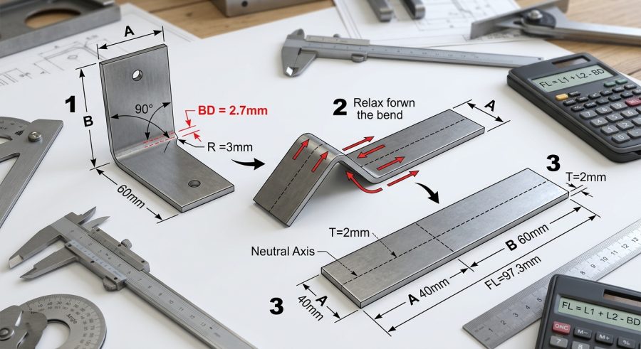
- Measure your material thickness and enter it, using millimeters or inches consistently across every field.
- Enter the Inside Bend Radius as measured on the concave (inside) surface of the bend, not the outside.
- Set the Bend Angle in degrees, measuring how far the flange rotates away from its original flat position.
- Choose a K-factor between 0.30 and 0.50 based on your material thickness and bending method.
- Enter Flange Length A, Flange Length B, and any Additional Flange Length for parts with more than two legs.
- Enter the Number of Bends, then read the Bend Allowance, Setback, Bend Deduction, Neutral Axis Offset, and Total Flat Length results.
Entering Thickness, Radius, Angle and Flange Data
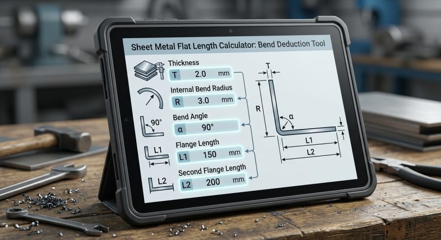
Material Thickness is the gauge of your sheet, entered in millimeters or inches. Use the same unit for every length field on the page.
Inside Bend Radius is the radius on the concave side of the bend, formed by your punch or die, not the outside radius of the part.
Bend Angle is how far the flange rotates from flat, in degrees. A simple L-bracket uses 90 degrees; shallower or sharper bends use other values up to 180.
K-Factor is a decimal between about 0.30 and 0.50 that locates the neutral axis relative to the inside surface. It depends on material type, thickness, and bending method.
Flange Length A and Flange Length B are the two main leg lengths measured from the part edge to the bend tangent line. Additional Flange Length lets you add the combined length of any extra legs on parts with more than two flanges.
Number of Bends tells the calculator how many identical bends to subtract deduction for, assuming each bend shares the same angle, radius, thickness, and K-factor.
Bend Allowance, Deduction and Flat Length Math
Let T be thickness, R be inside bend radius, A be the bend angle in degrees, and K be the K-factor. The angle in radians is A times 3.14159265 divided by 180.
Bend Allowance equals the angle in radians times (R plus K times T). This is the arc length of material consumed by the bend along the neutral axis.
Setback equals (R plus T) times the tangent of half the bend angle in radians. This is the distance from the bend tangent point to the theoretical sharp corner.
Bend Deduction equals two times setback minus bend allowance. This is the amount subtracted from the sum of flange lengths for each bend.
Neutral Axis Offset equals K times T, showing how far the neutral bend line sits from the inside surface.
Total Flat Length equals Flange Length A plus Flange Length B plus Additional Flange Length, minus the Number of Bends times the Bend Deduction. This assumes every bend on the part is identical; parts with mixed angles or radii need separate deduction calculations added manually.
Four Verified Flat Length Calculations
Example 1 (thin steel bracket, mm): T = 1 mm, R = 1 mm, angle = 90 degrees, K = 0.44, Flange A = 30 mm, Flange B = 30 mm, 1 bend. Bend Allowance = 1.5708 x (1 + 0.44) = 2.262 mm. Setback = (1+1) x tan(45) = 2 mm. Bend Deduction = 2×2 – 2.262 = 1.738 mm. Total Flat Length = 30 + 30 – 1.738 = 58.262 mm.
Example 2 (standard 2 mm bracket): T = 2 mm, R = 2 mm, angle = 90 degrees, K = 0.44, Flange A = 50 mm, Flange B = 50 mm, 1 bend. Bend Allowance = 1.5708 x (2 + 0.88) = 4.524 mm. Setback = (2+2) x tan(45) = 4 mm. Bend Deduction = 8 – 4.524 = 3.476 mm. Total Flat Length = 50 + 50 – 3.476 = 96.524 mm.
Example 3 (inch-based part): T = 0.075 in, R = 0.125 in, angle = 90 degrees, K = 0.44, Flange A = 2 in, Flange B = 1.5 in, 1 bend. Bend Allowance = 1.5708 x (0.125 + 0.033) = 0.248 in. Setback = (0.125+0.075) x tan(45) = 0.2 in. Bend Deduction = 0.4 – 0.248 = 0.152 in. Total Flat Length = 2 + 1.5 – 0.152 = 3.348 in.
Example 4 (multi-bend channel, mm): T = 1.5 mm, R = 3 mm, angle = 90 degrees, K = 0.44, Flange A = 40 mm, Flange B = 40 mm, Additional Flange Length = 80 mm, 3 bends. Bend Allowance = 1.5708 x (3 + 0.66) = 5.749 mm. Setback = (3+1.5) x tan(45) = 4.5 mm. Bend Deduction = 9 – 5.749 = 3.251 mm. Total Flat Length = 40 + 40 + 80 – (3 x 3.251) = 160 – 9.753 = 150.247 mm.
Typical K-Factor Ranges by Bending Method
| Bending Method | Typical K-Factor Range | Notes |
|---|---|---|
| Air bending | 0.33 to 0.40 | Partial die contact; common for thin low-carbon steel, but varies with tonnage and die opening |
| Bottoming | 0.40 to 0.45 | Full die contact gives more consistent, repeatable bend results |
| Coining | 0.45 to 0.50 | Material is forced fully into the die; tightest radius control but highest tonnage |
These ranges are general industry rules of thumb, not fixed values. Always confirm K-factor with a test bend for critical parts.
Reading Your Bend Allowance and Flat Length Output
Bend Allowance is the developed arc length the bend consumes along the neutral axis. Setback shows how far the bend tangent point sits from the theoretical sharp corner, useful for tooling and layout checks. Bend Deduction is the actual number subtracted from your flange sum for each bend. Neutral Axis Offset shows how close the neutral line sits to the inside surface, which shifts with thickness and K-factor. Total Flat Length is the main output: the flat blank size to cut before bending. All values are rounded to three decimal places and should be treated as planning estimates until confirmed with a physical test bend.
What Changes Your Flat Pattern Length
Material thickness affects bend allowance, setback, and neutral axis position, and is fully accounted for in every formula.
Inside bend radius changes both setback and bend allowance directly; a larger radius increases material consumed by the bend.
Bend angle scales the arc length and setback through the tangent and radian conversion, and is included in every result.
K-factor shifts the neutral axis location, changing bend allowance without changing setback, and is fully included in the math.
Springback from material grade and grain direction is not included and can require a slightly larger bend angle allowance in production.
Tooling and die selection, such as air bending versus bottoming, affects the real K-factor but is not automatically detected by the calculator.
Errors That Throw Off Flat Blank Sizing
- Mixing units: entering thickness in millimeters and flange length in inches breaks the math; keep every field in one unit system.
- Using outside radius: the formulas need inside bend radius, not the outside radius of the formed part.
- Measuring flanges to the sharp corner: flange lengths should be measured to the bend tangent point, not the theoretical outside corner.
- Guessing K-factor: picking an arbitrary K-factor without matching it to material and bending method can shift flat length noticeably.
- Assuming identical bends on mixed parts: the Number of Bends field assumes every bend shares the same angle, radius, and thickness.
- Ignoring springback: the calculator does not add springback correction, so tight-tolerance parts may need a small manual adjustment.
- Skipping a test bend: for production runs, always confirm the calculated flat length with a physical sample before cutting a full batch.
What This Tool Does Not Account For
This calculator uses the K-factor method for bend allowance and bend deduction. It assumes uniform material properties, a single K-factor applied across all bends, and no springback correction. It does not model air bending versus bottoming versus coining differences beyond the K-factor you choose, nor does it account for grain direction, tooling wear, or press tonnage. Real-world results vary by material grade, supplier, and shop equipment. For structural, safety-critical, or high-tolerance parts, an appropriately qualified engineer or fabricator should verify flat length with a physical test bend before committing to production.
Bend Allowance vs Bend Deduction Explained
Bend allowance is the arc length of material used up by the bend itself, measured along the neutral axis. Bend deduction is a different number: it is what you subtract from the sum of the flange lengths to get the flat length, because flange lengths are usually measured to the bend tangent point rather than to a sharp virtual corner. Bend deduction equals two times setback minus bend allowance, which is why both values appear as separate results in this calculator.
Handling Parts With More Than Two Flanges
Many real parts, like U-channels or hat sections, have three or more flanges and multiple bends. Enter your two main legs in Flange Length A and B, then add the combined length of any remaining legs into Additional Flange Length. Set Number of Bends to match the total bend count, keeping in mind the calculator assumes every bend shares the same thickness, radius, angle, and K-factor. Parts with different bend angles or radii at each bend need their deductions calculated and summed separately.
Choosing a K-Factor for Your Setup
K-factor is not a fixed material property; it shifts with thickness, bend radius, and bending method. Thin sheet bent with a wide air-bending die often uses a lower K-factor near 0.33, while thicker material bottomed or coined in a tight die often uses a higher K-factor near 0.45 or above. When exact shop data is unavailable, 0.44 is a commonly used mid-range starting point, but a test bend remains the most reliable way to confirm the right value for your material and setup.
Sheet Metal Bend Deduction Questions Answered
What is the difference between bend allowance and bend deduction?
Bend allowance is the arc length of material consumed along the neutral axis during the bend. Bend deduction is the amount subtracted from the sum of your flange lengths to get flat length, since flange lengths are measured to the bend tangent point rather than a sharp corner. Bend deduction equals two times setback minus bend allowance.
How do I choose the correct K-factor for different materials?
K-factor depends on material type, thickness, and bending method rather than a single fixed number. Air bending typically uses a lower K-factor, while bottoming or coining pushes it higher, often between 0.30 and 0.50. When you are unsure, a mid-range value like 0.44 is a common starting point, but a physical test bend gives the most accurate result.
Why does inside bend radius matter for flat length calculations?
Inside bend radius directly changes both setback and bend allowance, since a larger radius means more material is used to form the curve. The calculator requires inside radius, not outside radius, because the formulas are built around the neutral axis location relative to the inside surface.
Can this calculator handle parts with more than two bends?
Yes. Enter your first two flange lengths in Flange Length A and B, add any remaining leg lengths together in Additional Flange Length, and set Number of Bends to the total bend count. This works well when every bend shares the same thickness, radius, angle, and K-factor.
How accurate is the K-factor method compared to bend allowance tables?
The K-factor method is a widely used engineering approximation that works well for general planning and quoting. Shop-specific bend allowance tables built from real test bends on your own press and tooling are usually more precise, since they capture actual springback and die behavior that a generic formula cannot fully replicate.
What K-factor should I use if I do not know my exact bending setup?
A value around 0.44 is a common default for standard bottom bending of mild steel and aluminum at typical thicknesses. It is a reasonable planning estimate, but you should confirm it with a test bend whenever the part has tight tolerances or uses an unfamiliar material or die combination.
Does this calculator include springback correction?
No. The formulas here compute geometric bend allowance and deduction only. Springback varies by material grade, hardness, and grain direction, so production parts with tight angle tolerances typically need a small manual angle overbend added after test bending.
Can I mix millimeters and inches in the same calculation?
No. All length fields, including thickness, inside radius, and every flange length, must use the same unit system throughout the calculation. Mixing millimeters and inches in different fields will produce an incorrect flat length result.
Turning Bend Math Into Reliable Flat Blanks
Getting the flat length right before you cut is what separates a clean brake press job from a scrapped blank. This calculator applies the standard K-factor method to turn thickness, radius, angle, and flange data into bend allowance, setback, bend deduction, and total flat length. Treat the output as a solid planning estimate, then confirm critical or tight-tolerance parts with a physical test bend before running a full production batch.
