
This calculator estimates weld metal volume for fillet or groove welds from joint geometry, then converts that volume into weld metal weight and estimated filler metal needed after accounting for deposition efficiency and waste. Enter weld length, geometry, density, and efficiency values below (all linear inputs in the same unit, mm recommended) to instantly see volume, weight, and consumable estimates.
Weld Metal Volume Calculator: Volume, Weight & Filler Estimate
Estimate fillet and groove weld metal volume, deposited weight, and filler metal needed from joint geometry, density, and deposition efficiency.
What This Weld Volume and Filler Estimator Covers
This tool estimates how much weld metal a fillet or groove weld will consume by turning joint geometry into a cross-sectional area, then multiplying by weld length to get volume. It also converts that volume into deposited weight and an estimated purchase weight of filler metal, factoring in deposition efficiency and waste.
It helps welders, fabrication estimators, and QA/QC staff plan consumable orders, compare joint designs, or check that a proposed weld size is reasonable before cutting steel. Results are geometric estimates based on simplified shape models, not exact measurements of an actual completed weld, so treat them as planning numbers rather than inspection data.
Steps to Estimate Weld Volume and Filler Weight
- Enter the weld length in millimeters, measuring the full run of continuous weld you plan to make.
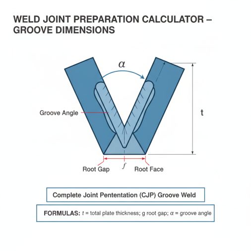
- For fillet welds, enter the fillet leg size and leave groove fields at zero. For groove (butt) welds, enter groove depth, included angle, and root gap, and leave fillet leg size at zero.
- Enter the cap reinforcement height and width if your weld has a raised bead above the plate surface, or leave them low if the pass is flush.
- Enter the number of weld passes to see volume and weight per pass for multi-pass joints.
- Confirm the weld metal density (default 7.85 g/cm3 for mild steel) and adjust deposition efficiency and waste allowance to match your welding process.
- Review the cross-sectional area, total volume, weight, and estimated filler metal results below the inputs.
Understanding Each Joint and Process Input
Weld Length (mm): the total length of the continuous weld bead or joint run. This scales the cross-sectional area into a total volume.
Fillet Leg Size (mm): used only for fillet welds. It sets the two equal legs of the right-triangle weld cross-section. Enter 0 for groove welds.
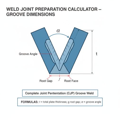
Groove Depth (mm): the depth of the beveled groove face on a butt joint, not counting any root face. Enter 0 for pure fillet welds.
Included Groove Angle (degrees): the total angle between the two beveled groove faces on a V-groove joint, typically between 30 and 90 degrees.
Root Gap (mm): the opening left between the two plates at the root of the joint, which fills with weld metal.
Cap Reinforcement Height and Width (mm): the height and width of the raised weld cap above the plate surface. Set both to 0 for a flush pass.
Number of Weld Passes: how many individual passes make up the joint, used to estimate volume and weight per pass.
Weld Metal Density (g/cm3): the density of the deposited weld metal. The default of 7.85 g/cm3 matches typical mild steel; adjust for stainless steel, aluminum, or other alloys.
Deposition Efficiency (%): the percentage of purchased filler metal that actually becomes deposited weld metal, after spatter, slag, and stub-end losses.
Waste/Contingency Allowance (%): an extra buying margin on top of deposition efficiency to cover arc strikes, trial runs, and handling losses.
How Fillet, Groove, and Cap Volumes Are Calculated
Fillet area assumes an equal-leg right triangle: area equals 0.5 times fillet leg size squared, in square millimeters. This models a standard flat-face fillet weld with no added convexity.
Groove area combines two parts. The beveled wedge contributes groove depth squared times the tangent of half the included angle (converted from degrees to radians). The root gap contributes a rectangle equal to root gap times groove depth. Together these estimate the metal needed to fill a simple single-V groove plus its root opening. U-grooves, J-grooves, and double-V joints are not modeled directly.
Cap reinforcement area uses a 0.6 shape factor times reinforcement width times reinforcement height, approximating the convex, roughly parabolic profile of a typical cap pass rather than a full rectangle.
Total cross-sectional area is the sum of the fillet, groove-plus-root, and reinforcement areas, in square millimeters.
Weld metal volume equals total cross-sectional area multiplied by weld length, then divided by 1000 to convert cubic millimeters into cubic centimeters, since 1 cm3 equals 1000 mm3.
Weld metal weight equals volume in cubic centimeters multiplied by weld metal density in grams per cubic centimeter, giving weight in grams.
Estimated filler metal needed divides deposited weight by deposition efficiency (as a decimal) and then multiplies by one plus the waste allowance (as a decimal), estimating the actual filler metal weight to purchase.
Volume and weight per pass simply divide the total volume or weight by the number of passes, assuming each pass deposits roughly equal metal.
Sample Calculations for Common Weld Joints
Example 1: Fillet weld only. Given: fillet leg size 8 mm, groove depth 0 mm, weld length 1000 mm, reinforcement height 2 mm, width 14 mm, 2 passes, density 7.85 g/cm3, efficiency 70%, waste 10%.
Formula: area = 0.5 x leg^2 + reinforcement area.
Substitution: area = 0.5 x 8^2 + 0.6 x 14 x 2 = 32 + 16.8 = 48.8 mm2.
Calculation: volume = 48.8 x 1000 / 1000 = 48.8 cm3; weight = 48.8 x 7.85 = 383.08 g; filler = 383.08 / 0.70 x 1.10 = 601.98 g.
Final result: about 48.8 cm3, 383.1 g deposited, 602.0 g filler metal, 191.5 g per pass.
Example 2: Groove weld only. Given: groove depth 12 mm, angle 60 degrees, root gap 3 mm, weld length 800 mm, no fillet or cap, 3 passes, density 7.85 g/cm3, efficiency 60%, waste 15%.
Formula: area = depth^2 x tan(angle/2) + root gap x depth.
Substitution: area = 12^2 x tan(30) + 3 x 12 = 144 x 0.5774 + 36 = 83.16 + 36 = 119.16 mm2.
Calculation: volume = 119.16 x 800 / 1000 = 95.33 cm3; weight = 95.33 x 7.85 = 748.31 g; filler = 748.31 / 0.60 x 1.15 = 1434.3 g.
Final result: about 95.3 cm3, 748.3 g deposited, 1434.3 g filler metal, 249.4 g per pass.
Example 3: Default combined joint. Given: fillet leg 6 mm, groove depth 10 mm, angle 60 degrees, root gap 2 mm, cap height 1.5 mm, width 12 mm, weld length 500 mm, 1 pass, density 7.85 g/cm3, efficiency 65%, waste 10%.
Formula: total area = fillet area + groove area + cap area.
Substitution: area = 18 + 57.74 + 20 + 10.8 = 106.54 mm2.
Calculation: volume = 106.54 x 500 / 1000 = 53.27 cm3; weight = 53.27 x 7.85 = 418.1 g; filler = 418.1 / 0.65 x 1.10 = 707.6 g.
Final result: about 53.3 cm3, 418.1 g deposited, 707.6 g filler metal needed.
Example 4: Deep multi-pass groove weld. Given: groove depth 20 mm, angle 45 degrees, root gap 1.5 mm, cap height 3 mm, width 16 mm, weld length 1500 mm, 6 passes, density 7.85 g/cm3, efficiency 68%, waste 12%.
Formula: total area = groove wedge + root + cap.
Substitution: area = 20^2 x tan(22.5) + 1.5 x 20 + 0.6 x 16 x 3 = 165.69 + 30 + 28.8 = 224.49 mm2.
Calculation: volume = 224.49 x 1500 / 1000 = 336.73 cm3; weight = 336.73 x 7.85 = 2643.3 g; filler = 2643.3 / 0.68 x 1.12 = 4353.7 g.
Final result: about 336.7 cm3, 2643.3 g deposited, 4353.7 g filler metal, 440.6 g per pass.
Typical Fillet Sizes and Their Cross-Sectional Areas
| Fillet Leg Size (mm) | Cross-Sectional Area (mm2) | Assumption |
|---|---|---|
| 3 | 4.50 | Equal-leg right triangle, no cap |
| 4 | 8.00 | Equal-leg right triangle, no cap |
| 5 | 12.50 | Equal-leg right triangle, no cap |
| 6 | 18.00 | Equal-leg right triangle, no cap |
| 8 | 32.00 | Equal-leg right triangle, no cap |
| 10 | 50.00 | Equal-leg right triangle, no cap |
| 12 | 72.00 | Equal-leg right triangle, no cap |
Reading Your Volume, Weight, and Filler Results
The total cross-sectional area shows the combined fillet, groove, and cap area in square millimeters, which is useful for comparing joint designs before committing to a weld size.
The weld metal volume converts that area into cubic centimeters using weld length, giving the raw amount of metal that must fill the joint.
The weld metal weight multiplies volume by density, giving the actual deposited weight in grams. This number reflects what ends up in the joint, not what you buy.
The estimated filler metal needed is the more practical number for ordering electrodes or wire, since it adds back the losses from deposition efficiency and a waste allowance.
Volume and weight per pass help you judge whether a joint is realistic for the chosen pass count and electrode size. All results are rounded to the decimal places shown and represent estimates, not verified measurements of a finished weld.
Joint Variables That Change Filler Consumption
Groove angle and depth: larger included angles and deeper grooves sharply increase wedge volume because the tangent term grows quickly past about 60 degrees. This calculator accounts for this directly.
Root gap: even a small increase in root opening adds a proportional rectangular volume across the full weld length. This is included in the groove area formula.
Cap reinforcement: a wider or higher cap pass adds real, often underestimated, volume. The 0.6 shape factor is a reasonable average but will not match every bead profile exactly.
Deposition efficiency and waste: these do not change the physical weld but strongly affect how much filler metal you need to buy. Lower efficiency processes require proportionally more purchased consumable, which the filler metal result reflects.
Material density: switching from mild steel to stainless steel or aluminum changes weight results directly, since density varies by alloy and is not fixed by this calculator.
Number of passes: this only divides totals evenly; it does not model uneven pass sizes such as a larger root pass followed by smaller fill passes.
Estimating Errors That Skew Filler Orders
- Mixing units: entering some dimensions in inches and others in millimeters breaks the math. Keep every linear input in the same unit, ideally millimeters.
- Leaving unused fields at their default: for a pure fillet weld, set groove depth and root gap to 0, and for a pure groove weld, set fillet leg size to 0, or the areas will add incorrectly.
- Double-counting reinforcement: if your groove depth already includes the cap, do not also add a large reinforcement height, or the volume will be overstated.
- Guessing deposition efficiency: using an unrealistic efficiency value, such as 95% for a manual stick process, will understate the filler metal you actually need to order.
- Ignoring root gap on tight joints: skipping a small but real root opening can meaningfully understate groove weld volume on longer joints.
- Using volume as a final acceptance value: this tool estimates planning volume, not a certified as-built measurement for inspection or code compliance.
- Forgetting waste allowance: ordering exactly the deposition-efficiency-adjusted amount with no contingency often leaves a job short of consumable.
What This Estimate Does Not Replace
This calculator uses simplified geometric models for fillet, single-V groove, root gap, and cap reinforcement areas. It does not model U-grooves, J-grooves, double-sided bevels, unequal-leg fillets, or irregular cap profiles, and results for those joint types will be approximate at best.
Deposition efficiency and waste allowance are user-supplied planning estimates that vary by welding process, position, electrode type, and operator skill; actual consumable use on the job may differ from the calculated value.
Results assume consistent joint geometry along the full weld length and do not account for gouging, backgouging, weave width variation, or repair passes. This tool does not replace an approved Welding Procedure Specification, qualified welding engineering review, or code-required joint design calculations. Always verify critical dimensions and consumable requirements against project specifications and applicable welding codes before fabrication or procurement.
Choosing Between Fillet and Groove Inputs
For a fillet weld, enter a fillet leg size and set groove depth, groove angle, and root gap to 0. For a groove or butt weld, enter groove depth, included angle, and root gap, and set fillet leg size to 0. Combination joints, such as a fillet weld reinforcing a groove weld root, can use both sets of inputs together, since the calculator simply adds the resulting areas.
Planning Multi-Pass Weld Sequences
The volume and weight per pass results divide the total evenly across the number of passes entered. Real multi-pass joints often use a smaller root pass followed by larger fill and cap passes, so treat the per-pass figures as an average guide for planning electrode changes and estimating time per pass, not as a fixed schedule for each individual bead.
Turning Weight Into a Consumable Order
Once you have the estimated filler metal weight in grams, convert it to the packaging your supplier uses, such as kilograms of wire or number of electrode boxes, by dividing by the container weight. Because the filler metal result already includes deposition efficiency and a waste allowance, it is generally more appropriate for ordering than the raw deposited weight, which only reflects metal actually placed in the joint.
Weld Volume and Filler Estimate Questions
What density should I use for stainless steel or aluminum welds?
Replace the default 7.85 g/cm3 mild steel value with the density of your actual filler alloy, roughly 7.9 to 8.0 g/cm3 for common stainless steels and about 2.7 g/cm3 for aluminum, since weight scales directly with density.
Why do I need both deposition efficiency and a waste allowance?
Deposition efficiency models normal process losses such as spatter, slag, and stub ends, while the waste allowance is a separate buying margin for arc strikes, setup runs, and handling losses, so combining both gives a more realistic purchase quantity.
Can this calculator handle U-groove or J-groove joints?
Not directly. The groove formula models a simple single-V bevel plus a rectangular root gap, so U-grooves, J-grooves, and double-sided bevels will need a manually adjusted or separate area calculation.
How do I model a double-V or double-bevel groove weld?
You can approximate it by running the calculator twice, once for each groove face with its own depth and angle, and adding the two resulting volumes or weights together, since the underlying wedge formula only handles one bevel at a time.
Why is my estimated filler metal much higher than the deposited weight?
This gap widens as deposition efficiency drops or waste allowance rises. For example, a 60% efficient process with 15% waste needs roughly 1.9 times the deposited weight in purchased filler metal, which is expected behavior, not an error.
Does the number of passes change the total weld volume?
No. Total volume and total weight depend only on joint geometry, weld length, and density. The number of passes only divides those totals to estimate an average volume and weight per individual pass.
Is the cap reinforcement area exact for every weld profile?
No, it uses a fixed 0.6 shape factor as a general approximation of a convex cap bead. Flatter or more peaked caps will have a slightly smaller or larger actual area than this estimate.
Can I use this for cost estimating in addition to weight estimating?
Yes, once you have the estimated filler metal weight in grams, you can multiply it by your filler metal's price per gram or per kilogram to build a rough consumable cost estimate for the joint.
Putting Your Weld Volume Estimate to Work
This calculator turns basic joint geometry into practical numbers: cross-sectional area, total volume, deposited weight, and filler metal to order. Use it early in job planning to size consumable purchases, compare fillet versus groove designs, and sanity-check pass counts, while always confirming final joint details against your approved welding procedure and applicable code requirements.
