
This calculator estimates the required shell plate thickness for a vertical storage tank course using the API 650 one-foot method, combining tank diameter, liquid height, specific gravity, allowable stress, joint efficiency, and corrosion allowance. It returns the design thickness, hydrostatic test thickness, and the governing value. The governing thickness is the larger of the two and determines the plate you should specify, subject to verification by a qualified engineer.
Tank Shell Thickness Calculator: API 650 Design & Test
Calculate API 650 tank shell design thickness, hydrostatic test thickness, and governing plate size using the one-foot method.
Estimating Shell Course Thickness for API 650 Tanks
This tank shell thickness calculator finds the minimum plate thickness needed for one course of a vertical, above-ground storage tank shell using the API 650 one-foot method. It is built for tank designers, mechanical and civil engineers, fabrication estimators, and students checking preliminary shell sizing before a full code review.
You enter tank diameter, liquid height, specific gravity, allowable stresses, joint efficiency, and corrosion allowance. The calculator returns a design thickness, a hydrostatic test thickness, the governing value, and a rounded nominal plate size. Because this applies a simplified code formula rather than a full API 650 review, treat the output as a planning-level estimate, not a certified design value.
Steps to Calculate Shell Thickness in Minutes
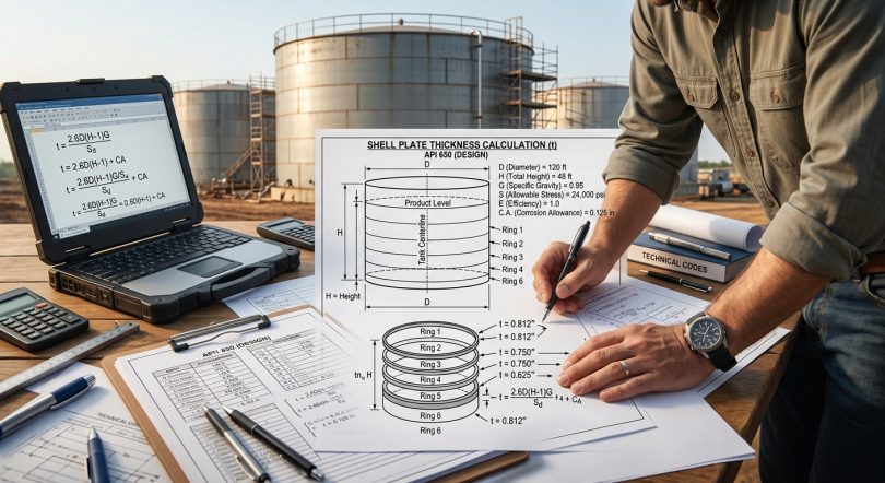
Follow these steps to estimate shell thickness for one course:
- Enter the tank diameter in meters.
- Enter the design liquid height above the course being checked, in meters.
- Enter the specific gravity of the stored liquid, with water equal to 1.00.
- Enter the allowable design stress and allowable hydrostatic test stress for the plate material, in MPa.
- Select the weld joint efficiency matching your radiography level.
- Enter the corrosion allowance in millimeters and read the four results.
Understanding Each Tank and Material Input
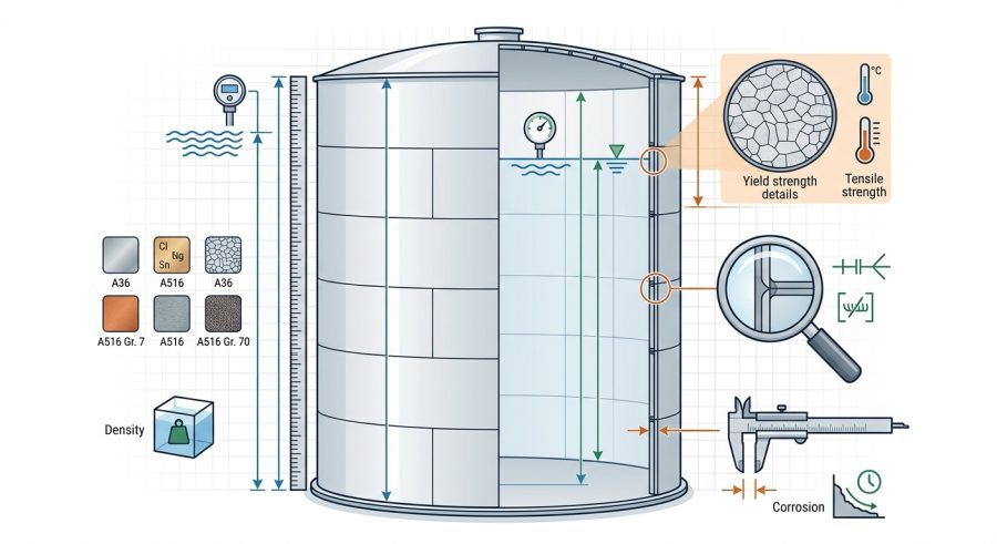
Tank Diameter (m) is the nominal inside diameter of the tank shell. Larger diameters increase hoop stress and required thickness proportionally.
Design Liquid Height (m) is the height of stored liquid above the shell course being checked, measured to the top of the course or overflow level, whichever applies to your design case.
Liquid Specific Gravity compares the stored liquid density to water. Water is 1.00; lighter fuels are often below 1.00, and dense chemicals can exceed 1.00.
Allowable Design Stress (MPa) is the permitted stress for the shell material at the design condition, taken from the applicable material specification and code table.
Allowable Hydrostatic Test Stress (MPa) is the permitted stress used to check the shell when the tank is filled with water for testing. It is often set below the design stress value.
Weld Joint Efficiency reflects the level of radiographic inspection applied to the shell butt welds. Full radiography allows the highest efficiency and thinnest plate; no radiography requires thicker plate.
Corrosion Allowance (mm) is extra thickness added to the design case only, to allow for expected metal loss over the tank’s service life.
The One-Foot Method Formulas Explained
The calculator uses the API 650 one-foot method, which checks stress at a point roughly one foot (0.3 m) above the bottom of the shell course, where hydrostatic pressure is slightly lower than at the very bottom.
Variables: D = tank diameter (m), H = design liquid height (m), G = specific gravity, S = allowable design stress (MPa), St = allowable hydrostatic test stress (MPa), E = joint efficiency, CA = corrosion allowance (mm).
Design thickness: td = (4.9 x D x (H – 0.3) x G) / (S x E) + CA
Hydrostatic test thickness: tt = (4.9 x D x (H – 0.3)) / (St x E)
Governing thickness is the larger of td and tt, since the shell must satisfy both conditions.
Recommended nominal thickness rounds the governing value up to the nearest 0.5 mm plate increment, since mills typically supply plate in fixed steps.
The constant 4.9 combines the hydrostatic pressure of water-based liquids with unit conversions for meters, MPa, and millimeters. If you work in US customary units (feet, psi, inches), the equivalent one-foot method formula uses a constant of 2.6 in place of 4.9, with diameter and height in feet and stress in psi.
The test thickness formula assumes the tank is filled with water, so it does not include a specific gravity term or corrosion allowance, matching standard code practice.
Four Sample Shell Thickness Calculations
Example 1 — Small water storage tank
Given: D = 10 m, H = 10 m, G = 1.00, S = 160 MPa, St = 145 MPa, E = 1.00, CA = 1.5 mm.
Formula: td = (4.9 x 10 x 9.7 x 1.00) / (160 x 1.00) + 1.5
Substitution: td = 475.3 / 160 + 1.5
Calculation: td = 2.97 + 1.5 = 4.47 mm; tt = 475.3 / 145 = 3.28 mm
Final result: Governing thickness = 4.47 mm; recommended nominal plate = 4.5 mm.
Example 2 — Mid-height course, spot-radiographed weld
Given: D = 36 m, H = 14.6 m, G = 0.90, S = 155 MPa, St = 140 MPa, E = 0.85, CA = 1.5 mm.
Formula: td = (4.9 x 36 x 14.3 x 0.90) / (155 x 0.85) + 1.5
Substitution: td = 2271.35 / 131.75 + 1.5
Calculation: td = 17.24 + 1.5 = 18.74 mm; tt = 2523.72 / 119 = 21.21 mm
Final result: Governing thickness = 21.21 mm; recommended nominal plate = 21.5 mm.
Example 3 — Small tank with minimal corrosion allowance
Given: D = 6 m, H = 6 m, G = 1.00, S = 137 MPa, St = 137 MPa, E = 1.00, CA = 1.0 mm.
Formula: td = (4.9 x 6 x 5.7 x 1.00) / (137 x 1.00) + 1.0
Substitution: td = 167.58 / 137 + 1.0
Calculation: td = 1.22 + 1.0 = 2.22 mm; tt = 167.58 / 137 = 1.22 mm
Final result: Governing thickness = 2.22 mm; recommended nominal plate = 2.5 mm.
Example 4 — Dense corrosive liquid, no radiography
Given: D = 12 m, H = 8 m, G = 1.83, S = 160 MPa, St = 145 MPa, E = 0.70, CA = 3.0 mm.
Formula: td = (4.9 x 12 x 7.7 x 1.83) / (160 x 0.70) + 3.0
Substitution: td = 828.55 / 112 + 3.0
Calculation: td = 7.40 + 3.0 = 10.40 mm; tt = 452.76 / 101.5 = 4.46 mm
Final result: Governing thickness = 10.40 mm; recommended nominal plate = 10.5 mm.
Typical Minimum Shell Thickness by Tank Diameter
The table below shows typical minimum nominal shell thickness values commonly referenced for atmospheric storage tanks, excluding annular plates. These figures vary by code edition and tank category, so always confirm against the current API 650 edition and your project specification.
| Tank Diameter Range | Typical Minimum Nominal Thickness | Assumption |
|---|---|---|
| Less than 15 m | 5 mm | Carbon steel shell, standard service |
| 15 m to 36 m | 6 mm | Carbon steel shell, standard service |
| 36 m to 60 m | 8 mm | Carbon steel shell, standard service |
| 60 m or more | 10 mm | Carbon steel shell, standard service |
Reading Your Design, Test, and Nominal Results
The Design Shell Thickness is the minimum plate thickness needed to hold the stored liquid under normal operating conditions, including the corrosion allowance.
The Hydrostatic Test Shell Thickness is the minimum thickness needed when the tank is filled with water for testing, calculated without corrosion allowance or specific gravity.
The Governing Shell Thickness is the larger of the two values above and represents the true minimum thickness the plate must meet.
The Recommended Nominal Plate Thickness rounds the governing value up to the nearest practical 0.5 mm increment, since plate is usually ordered in fixed sizes. All results are estimates; the final specified thickness must also meet any applicable minimum nominal thickness rule and be confirmed by a qualified engineer.
What Changes Required Shell Thickness
Tank diameter has a direct, linear effect on thickness and is fully accounted for in the formula. Liquid height above the course also increases thickness linearly and is included as entered.
Specific gravity raises the design thickness for denser liquids and is applied only to the design case, matching standard practice.
Allowable stress values depend on plate material grade and code table selection; the calculator uses whatever values you enter, so accuracy depends on using the correct material data.
Joint efficiency reduces effective strength when welds are not fully radiographed, increasing required thickness. This is handled through the selectable field.
Corrosion allowance adds a fixed thickness margin to the design case only. Factors not accounted for include wind load, seismic load, nozzle reinforcement, roof loading, and foundation settlement, all of which require separate engineering checks.
Frequent Errors When Sizing Shell Plates
- Using total tank height instead of course height: the one-foot method applies to the liquid height above each specific course, not the full tank height, when checking upper courses.
- Mixing unit systems: entering feet or psi values into a metric-only formula gives an incorrect result; convert to meters, MPa, and millimeters first.
- Applying corrosion allowance to the test case: standard practice adds corrosion allowance only to the design thickness, not the hydrostatic test thickness.
- Choosing the wrong joint efficiency: selecting full radiography when welds are only spot-checked understates the required thickness.
- Forgetting to repeat the calculation per course: each shell course has a different liquid height and may need its own calculation.
- Using yield strength instead of allowable stress: the formula requires the code allowable stress value, not raw material yield or tensile strength.
- Ignoring the minimum nominal thickness rule: even if the calculated value is low, API 650 sets a minimum plate thickness by tank diameter that must still be met.
What This Tool Does Not Cover
This calculator applies only the API 650 one-foot method for a single shell course under hydrostatic loading. It does not check wind girders, seismic overturning, nozzle reinforcement, roof design, foundation loading, or the code’s minimum nominal thickness tables. It also does not verify material compatibility, allowable stress values, or joint efficiency classifications against the current API 650 edition.
Results depend entirely on the accuracy of the stress, specific gravity, and dimensional values you enter. Code requirements, allowable stresses, and minimum thickness rules can change between editions and may vary by jurisdiction. This tool is intended for preliminary estimation only. Any tank shell design must be reviewed and approved by a qualified engineer licensed to practice in your jurisdiction before fabrication or construction.
Calculating Multiple Courses on a Tall Tank
A tall tank has several shell courses stacked from bottom to top, and each course carries a different liquid height above it. To size a full shell, run this calculator once per course, using the liquid height measured from the design liquid level down to the bottom of that course. The bottom course, which carries the greatest liquid height, is usually the thickest, while upper courses become progressively thinner.
Converting Results to US Customary Units
This calculator works in meters, MPa, and millimeters. To perform the same calculation in feet, pounds per square inch, and inches, convert diameter and liquid height from meters to feet, convert allowable stress from MPa to psi, and replace the constant 4.9 with 2.6 in the one-foot method formula. The corrosion allowance and joint efficiency terms work the same way in either unit system.
Picking a Joint Efficiency for Your Weld Inspection Level
Joint efficiency reflects how much of the weld has been radiographically inspected. Fully radiographed butt welds use an efficiency of 1.00, spot radiography typically uses 0.85, and welds without radiography use 0.70. Choose the value that matches your actual inspection plan, since a lower efficiency always increases the required plate thickness. Fabrication estimators working on connected steel piping may also want to check a pipe weight per foot calculator when preparing a full material take-off for the project.
Shell Thickness Calculator Questions Answered
What is the API 650 one-foot method and why is it used for tank shell thickness?
It is a simplified hydrostatic design method from API 650 that calculates required shell thickness at a point about one foot (0.3 m) above the bottom of each course, where stress is slightly lower than at the very bottom. It is widely used because it gives a conservative, straightforward result for shell design.
What is the difference between design thickness and hydrostatic test thickness?
Design thickness uses the actual stored liquid specific gravity and includes corrosion allowance, representing normal operating conditions. Hydrostatic test thickness assumes the tank is filled with water for testing and excludes corrosion allowance. The larger of the two becomes the governing thickness.
How does corrosion allowance affect the final shell plate thickness?
Corrosion allowance is added only to the design thickness to account for expected metal loss over the tank's service life. A larger allowance increases the design thickness directly but does not change the hydrostatic test thickness calculation.
Which joint efficiency value should I choose for my weld inspection level?
Select 1.00 for fully radiographed butt welds, 0.85 for spot radiographed welds, or 0.70 for welds without radiography. Use the value that matches your actual inspection plan, since a lower efficiency increases required thickness.
Can this calculator be used for pressure vessels instead of atmospheric storage tanks?
No. This tool applies the API 650 one-foot method, which is written for atmospheric, vertical, above-ground storage tanks. Pressure vessels use different code rules, such as ASME Section VIII, and require a different thickness formula.
How do I calculate shell thickness for multiple courses on a tall tank?
Run the calculator separately for each course, entering the liquid height measured from the design liquid level down to the bottom of that specific course. Repeat for every course from bottom to top to build a complete shell thickness profile.
How do I convert this metric calculation to US customary units?
Convert diameter and liquid height from meters to feet and allowable stress from MPa to psi, then replace the constant 4.9 in the formula with 2.6, which is the standard one-foot method constant for US customary units.
What is the minimum shell thickness required by API 650 regardless of calculated result?
API 650 sets minimum nominal shell thickness values based on tank diameter, separate from the calculated hydrostatic thickness. Even if this calculator returns a lower number, the final plate must still meet the applicable code minimum, which should be confirmed against the current edition.
Using These Results in Your Tank Design
This calculator gives a fast, code-based estimate of shell plate thickness for one tank course using the API 650 one-foot method. It highlights the design thickness, test thickness, governing value, and a practical nominal plate size. Because a full tank design involves multiple courses, minimum thickness rules, and additional loading checks, use these results as a starting point and have the final shell design confirmed by a qualified engineer.
